When it comes to installing an electric fireplace in your living space, understanding the wiring diagram is crucial. It not only ensures your fireplace operates efficiently but also guarantees your safety and the longevity of the unit.
Mastering the wiring diagram can save you time, money, and help prevent potential hazards.
In this guide, we’ll break down the essentials of reading and interpreting wiring diagrams, making it easier for you to correctly install your heating unit without any damage or risk.
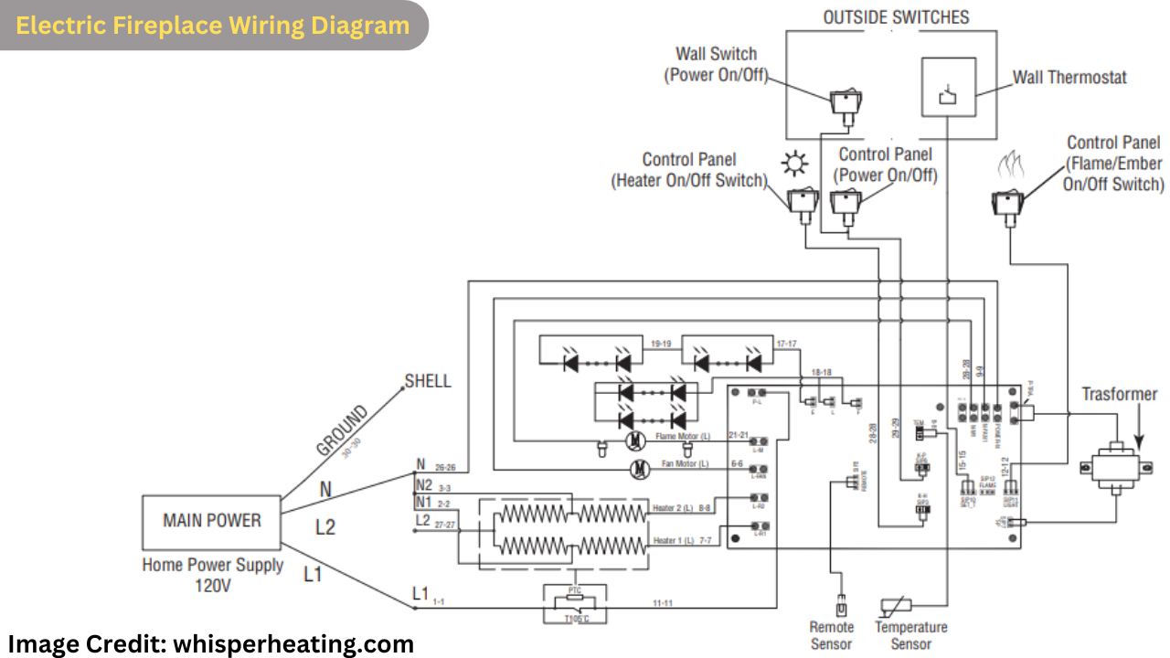
Electric Fireplace Wiring Diagram
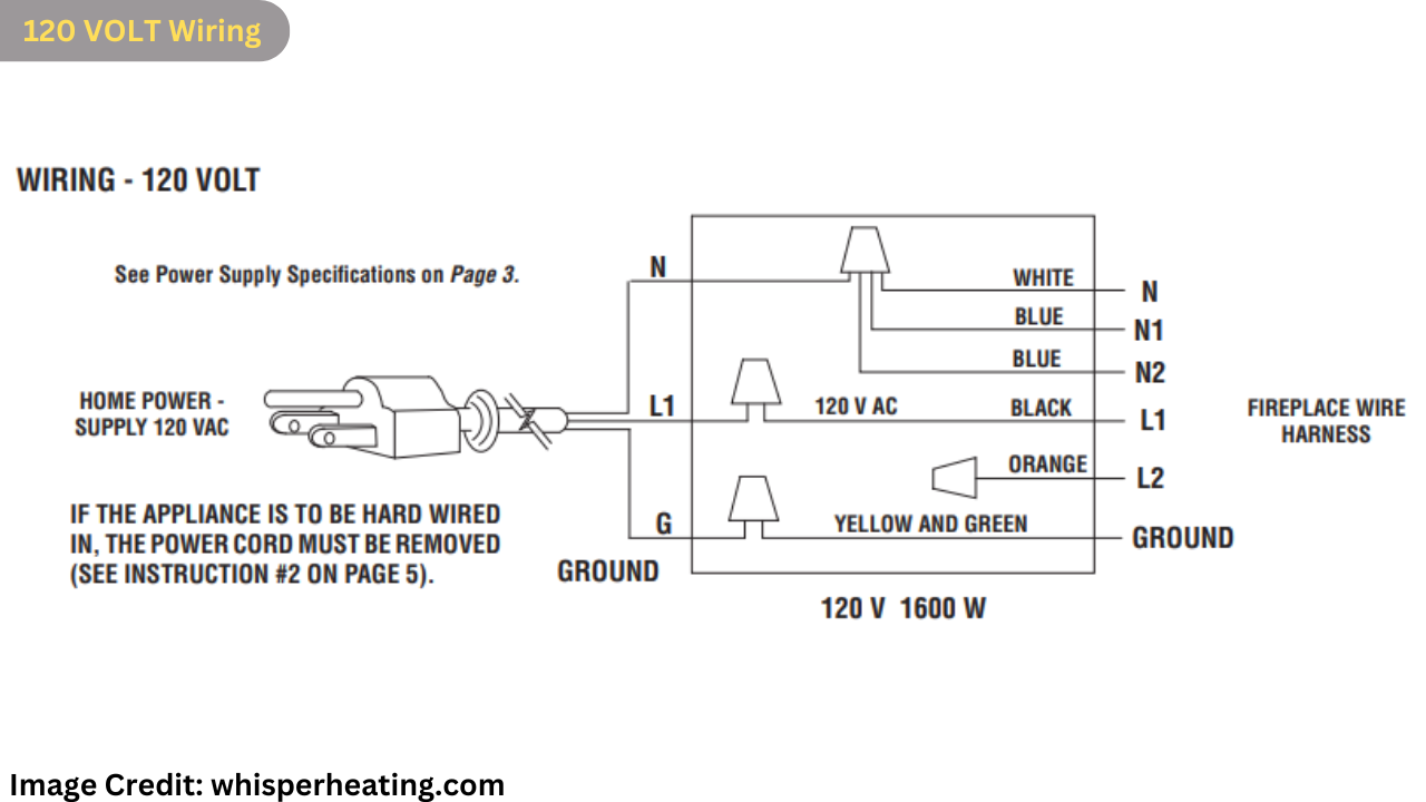
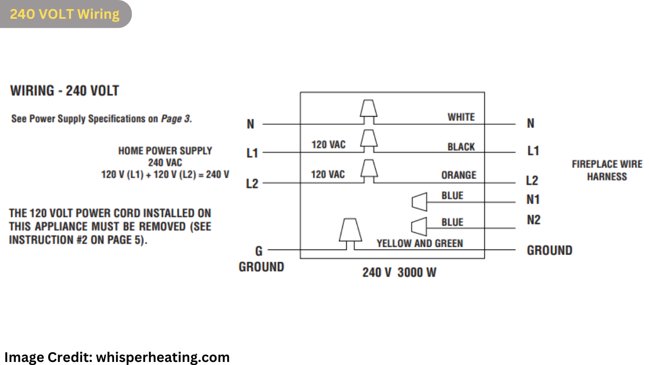
120-240 Volt Electric Fireplace Wiring Setup Guide
Note: This guide is based on the above wiring diagram. It is essential to follow the diagram carefully to avoid damage to your electric fireplace or any potential hazards. If you are not experienced with electrical work, please consult a professional.
Components and Color Coding:
- L1 (Black): Power
- L2 (Orange): Power
- G (Green): Ground
- N (White): Common
- N1 (Blue): Common
- N2 (Blue): Common
Wiring Instructions:
- Main Power Supply (Home Power Supply 120V):
- Connect the L1 (Black) wire from the main power supply to the L1 terminal on the fireplace.
- Connect the L2 (Orange) wire from the main power supply to the L2 terminal on the fireplace.
- Connect the N (White) wire from the main power supply to the neutral (N) terminal on the fireplace.
- Grounding:
- Connect the G (Green) wire from the main power supply to the ground terminal on the fireplace.
- Heating Element:
- The heating element has two connections: 1-2 and 1-5.
- 1-2: Connect to L1 (Black).
- 1-5: Connect to the terminal marked as 25.
- Control Panels:
- Heater On/Off Switch (Control Panel): Connect the switch terminals to the designated spots on the control board.
- Power On/Off Switch (Control Panel): Wire the power switch as indicated in the diagram.
- Flame/Ember On/Off Switch (Control Panel): Connect this switch according to the connections shown in the diagram.
- Wall Switch:
- Connect the wall switch to control the power on/off functionality.
- Ensure the wiring aligns with the provided diagram for accurate control.
- Wall Thermostat:
- Connect the thermostat as shown in the diagram to regulate the temperature.
- Transformer:
- Connect the transformer as per the wiring diagram, ensuring the correct input and output connections.
- Sensors:
- Remote Sensor: Wire the remote sensor to the indicated terminals for remote functionality.
- Temperature Sensor: Connect the temperature sensor to the designated spots to monitor and control heating.
Final Check:
- Double-check all connections against the diagram.
- Ensure that all wires are securely connected and insulated where necessary.
- Verify that the grounding is correctly established.
Power On:
- Once all connections are verified, you can power on the fireplace using the wall switch.
- Test all functions (heating, flame/ember effect, and remote control) to ensure everything is working as intended.
Important: Improper wiring can lead to malfunction or hazards. If unsure, consult with a certified electrician.
References:
- https://whisperheating.com/wp-content/uploads/2016/10/install-capella-33.pdf
- http://pdf.lowes.com/productdocuments/579c7268-6c86-4a05-8a09-713ce72a6350/12209145.pdf
Affiliate Disclosure: Fireplaceadviser.com is a participant in the Amazon Services LLC Associates Program. We may earn a commission when you click on certain links on this site and purchase.

Hello!! I am Jamal Khan. I often fix my home electric heaters and gas stove problems and research the common issues in the heating units to improve my knowledge and expertise. The aim of establishing fireplaceadviser.com is to share my expertise and knowledge with my audience.